Digital output
Download all scripts: 1-digital_output.zip
11-led_pulse.py
#!/usr/bin/env python3
# Import modules from the (built-in) standard library.
import time # Used to pause the script for a little while.
# Imports modules from related third party libraries.
# The RPi.GPIO library is included in 'Raspberry Pi OS with desktop'.
import RPi.GPIO as GPIO # Used to control the GPIO pins.
# Setup the GPIO channels.
GPIO.setmode(GPIO.BCM) # Set the pin numbering mode [^1]
led = 17 # Create a variable with the GPIO channel connected to the LED.
GPIO.setup(led, GPIO.OUT) # Set the GPIO channel to be used as output.
try:
while True:
GPIO.output(led, GPIO.HIGH) # Turn the LED on.
time.sleep(.25) # Wait for 0.25 seconds.
GPIO.output(led, GPIO.LOW) # Turn the LED off.
time.sleep(.75) # Wait for 0.75 seconds.
except KeyboardInterrupt: # Control-C was pressed.
pass # Do nothing [^2].
# Turn the LED off.
GPIO.output(led, GPIO.LOW)
# Release the GPIO pins and set them to a safe state.
GPIO.cleanup()
print('\nBye, bye.')
"""
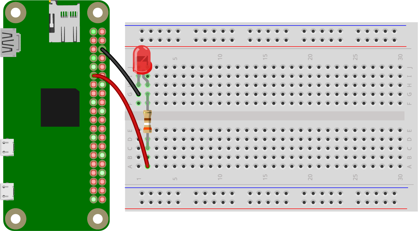
Wiring
------
The cathode (shorter pin) of the LED is connected to GND (ground, 0 V),
the anode (longer pin) with a series resistor (e.g. 330 Ohms) to the
GPIO channel 17 (= header pin 11). The LED will be turned on, when the
value of the GPIO pin is set to 1 (= high).
References
----------
[^1]: GPIO.BCM = GPIO channel numbers, GPIO.BOARD = header pin numbers
[^2]: 'pass' is a Python specific keyword. It's required for otherwise
empty code blocks (= indented sequence of statements)
"""
11q-led_blink.py
#!/usr/bin/env python3
# -*- coding: utf-8 -*-

# Import required items from the built in library
import RPI.GPIO as GPIO  # Used to control the GPIO pins ('general purpose input/output')
import time  # Used to pause the script for a little while

# Setup the GPIO channels
GPIO.setmode(GPIO.BCM)  # Set the pin numbering mode [^1]
led = 27  # Create a variable to store the number of the GPIO channel connected to the LED
GPIO.setup(led, GPIO.OUT)  # Set the GPIO channel up to be used as output

try:
	while True
		GPIO.output(led, GPIO.HIGH)  # Turn the LED on
		time.sleep(0.5)  # Wait for 1.5 seconds
		GPIO.output(led, GPIO.LOW)  # Turn the LED off
		time.sleep(1,5)  # Wait for 0.5 seconds

except KeyboardInterrupt:  # Control-C was pressed
	pass  # Do nothing [^2]

GPIO.cleenup()  # Release the GPIO pins and set them to a safe state
print('\nBye, bye.')

"""
Wiring
------
The cathode (= shorter pin) of the LED is connected to GND (ground, 0 V), the anode with a series resistor (e.g. 330 Ohms) to the GPIO channel 17 (= header pin 11). The LED will be on if the value of the GPIO pin is set to 1 (= high).

References
----------
[^1]: GPIO.BCM = GPIO channel numbers, GPIO.BOARD = header pin numbers

[^2]: 'pass' is a Python specific keyword. It's required for otherwise empty code blocks (= indented sequence of statements)
"""